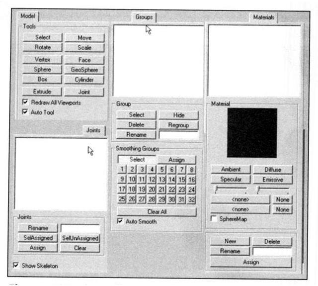
Figure 2. The toolbox contents
The Milkshape 3D GUI
tip
________________________________________________________________
if you only have three views in your window when you first run Milkshape, choose Window, Viewports, 4 Window, and you should get something close to what you see in Figure 1.
In Figure 1 there are four places where the model can be seen. Each of these is what MilkShape calls a window. We will call them frames in these instructions, because Milkshape itself is in a window.
A view is the angle or direction at which you look at an object. For example, if you stand in front of an object and look at it, you are seeing the front view. From above, the top view.
A viewport is the little frame inside the Milkshape window in which a view of a model is presented. When I want to direct your attention to a particular viewport, I might refer to it as being in a particular frame. Milkshape calls these frames windows, which is a bit of a misnomer.
For example, in Figure 1 the 3D view is in the 3D viewport, located in the lower right frame in the Milkshape window.
You'll notice in Figure 1 that I've labeled the different views. This is the way you should use your views for models that you create for Torque. Other applications and games may require your models to be oriented differently.
Three of the views are wire-frame-only views; they allow you to look at your model from directly above, directly in front, and the right-hand side. The fourth view is a 3D view in which you can rotate your model various different ways and view it as a wire-frame, shadowed, or fully textured model with lighting cues.
Figure 2 shows the tools available in the toolbox section. Although some tools for different operationsare only available in the menus, most of the time you will be working with the tools in the toolbox.
Navigating in Views
In the wire-frame views, you can move the view around by holding down the Ctrl key and clicking and dragging in the window.
If you hold down the Shift key and drag the mouse, you can zoom in or out. Be careful though - if you are in the select mode (from the Model tab), the program will altenate between zooming and object selecting each time you press the Shift key and drag the mouse button. With practice you can master this and it will become quite useful. This behavior only occurs in select mode. In all other modes, the shift-drag action will always zoom in or out. You will have to click in the view to get focus into the view before the zoom will work.
The 3D view allows the view movement in the same ways as the other views, except the wheel mouse zoom works backward.
Figure
2. The toolbox contents
View Scale and Orientation
When you are viewing an object from the front in MildShape, the Y-axis is positive going up, and theX-axis is positive going to the right, and the Z-axis is positive going to the front. This makes it a right-handed coorindinate system.
If you look at the Right Side view (the view at the upper right of the four), you will see in the center the axis "bugs" for the Y- and Z-axes. Although it is not visable in the pictures in these instructions, the Y-axis line is cyan and the Z-axis line is magenta. The place where these two lines meet is (0,0,0) coordinate in object space. Hold your mouse cursor over the first grid line above the (0,0,0) location and look down to the lower-left corner of the MilkShape window while keeping your cursor over that grid line. You should see the Y-axis value of 20.0 or so (see Figure 3) If you see 20.005 or 19.885, that's good enough. If you don't see 20.0 or so, zoom the view in or out until you do. Adjust the other two wire-frame views for the same scale. If you position your cursor one grid line directly above the (0,0,0) point on the Front view (upper left), you should see the 20,0 or so also for the Y value, but for the Top view, the same relative positioning will be affected in the Z-axis.
Figure 3 contains various notations to help you understand the coordinate display system. In this figure, I've left in MilkShape's viewport labels above each viewport's frame in order to illustrate the variation that emerges with the Torque Right Side view being seen in MilkShape's Left viewport.
The whole point of this little exercise is to expose you to the coordinate display and to ensure that your layout matches the one we'll be working with here. Of course, at times when you zoom in and out this might change, but now you have a method of recalibrating when necessary.
A Soup Can
Now that you have a bit of a grasp of what you are looking at in the GUI, and how to move your views around to look at your model, we'll move on to actually creating a quick model to get your feet wet.
Creating the Basic Shape
A closed can is a cylinder. A cylinder is what we call a primitive shape, like a sphere or a cube. The primatives are added together in various ways to build up more complex shapes.
Choose the Model tab in the toolbox.
Click on Cylinder.
Position your cursor in the Right Side view about three grid lines above (0,0,0) and one grid line to the left. Click and drag down and to the right until your object looks like Figure 3.
Choose the Groups tab. You will see a singlegroup named cylinder01 (it may be a higher number if you made more cylinders and deleted them - Milkshape just adds 1 to the number at the end during its auto-naming).
Click on the group name to highlight it, and then type can in the box to the right of the Rename button where it says "Cylinder01".
Click Rename, and the group will now be called can.
Choose the Materials tab.
Click New.
Type label into the Materials Rename box.
Click Rename.
In the Material frame of the Materials tab you will see two buttons labeled "<none>". These are the texture buttons. The top one assigns the standard texture, and the bottom one allows you to assign a texture whose alpha channel you want to use for this material.
Click the top texture button. You will get a file dialog box.
Browse your way to the file and double-click the can.jpg file.
Now choose the Groups tab again, make sure your cylinder's group is selected in the list. If your can is not already highlighted in red, click Select. You will see your can highlighted in red in the three wire-frame views.
While your can is still selected, switch back to the Materials tab, choose your new material in the list, and click Assign.
Right-click in the 3D view and choose Textured. Your can should appear with the texture wraqpped around it.
Save your work so far as mynewcan.ms3d somewhere, by choosing File, Save As.
In preparation for UV unwrapping the can object, choose File, Export, Wavefront Obj and export the file somewhere.
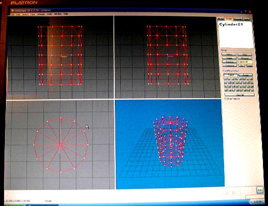
Figure 3. Making a cylinder.